System Schematic
This section details the hardware architecture of the Engine Health Monitoring System.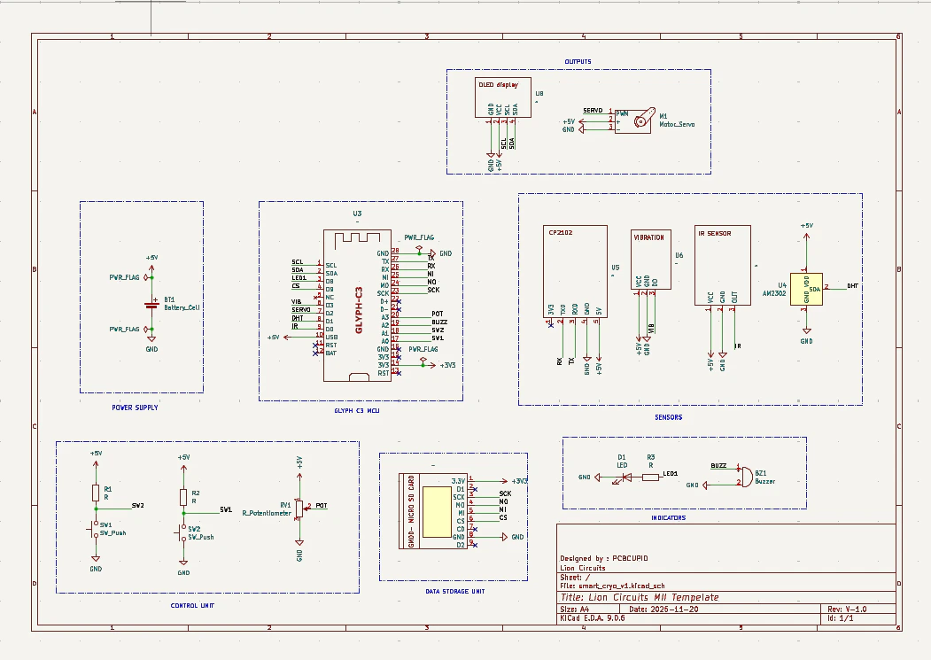
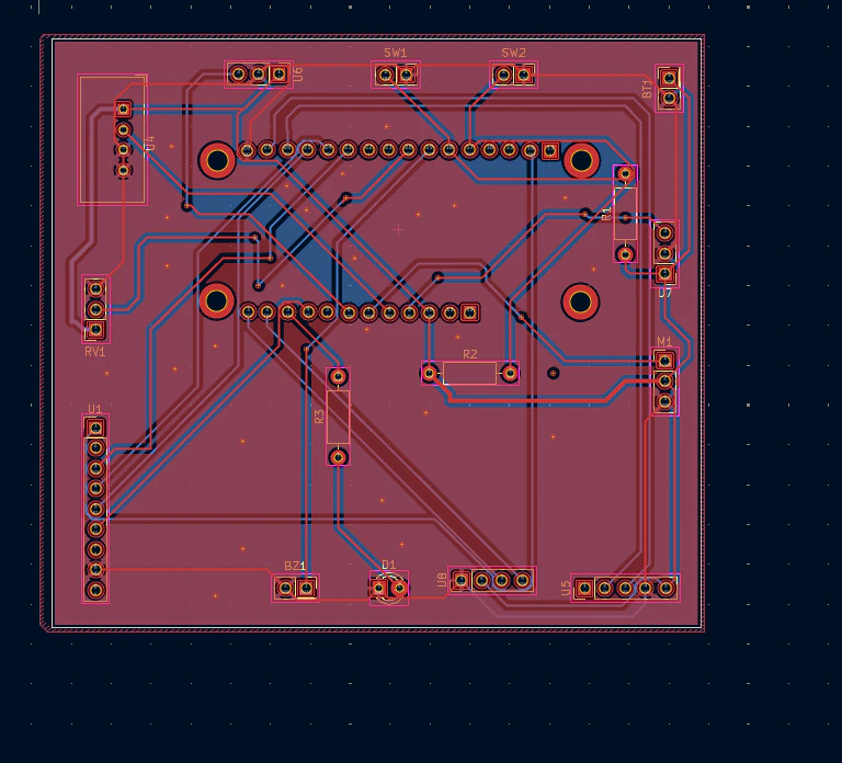
PCD DESIGN FILES :https://drive.google.com/file/d/1Ob3oV0ZkFJvhTSdvn7NcoHR1MbDIHHQQ/view?usp=sharingPrinted Version Of PCB:

System Design & Brains
The board uses the GLYPH-C3 (ESP32-C3) as its brain, providing wireless data tracking and low power use. It is built to monitor a rocket engine like a “digital doctor.”- Sensors: Tracks shaking (vibration), speed (RPM), and heat (temperature).
- Controls: Uses a knob (potentiometer) and two buttons to navigate the screen.
- Alerts: Features a screen (OLED) for data, plus a buzzer and LED for emergency warnings.
- Extras: Includes an SD card to save flight data and a motor (servo) to control fuel valves.
PCB Layout Features
The board was designed in KiCad with a focus on being “space-ready”:- Tough Build: It uses two layers and thick power lines to handle high electricity without overheating.
- Shielding: Large copper areas (ground planes) protect against electrical noise and keep the chip cool.
- Smart Placement: Sensors are placed on the edges for easy mounting and to keep them away from the heat of the main chip.
- Secure Mounting: Features large holes so it can be bolted tightly into a protective box to survive high-speed rocket vibrations.
Component Key
- MCU: GLYPH-C3
- Sensors: Vibration, IR, and DHT22
- Storage: Micro SD Card Slot
- Output: OLED
- Controls: Push_Button and 1K Trimmer Pot